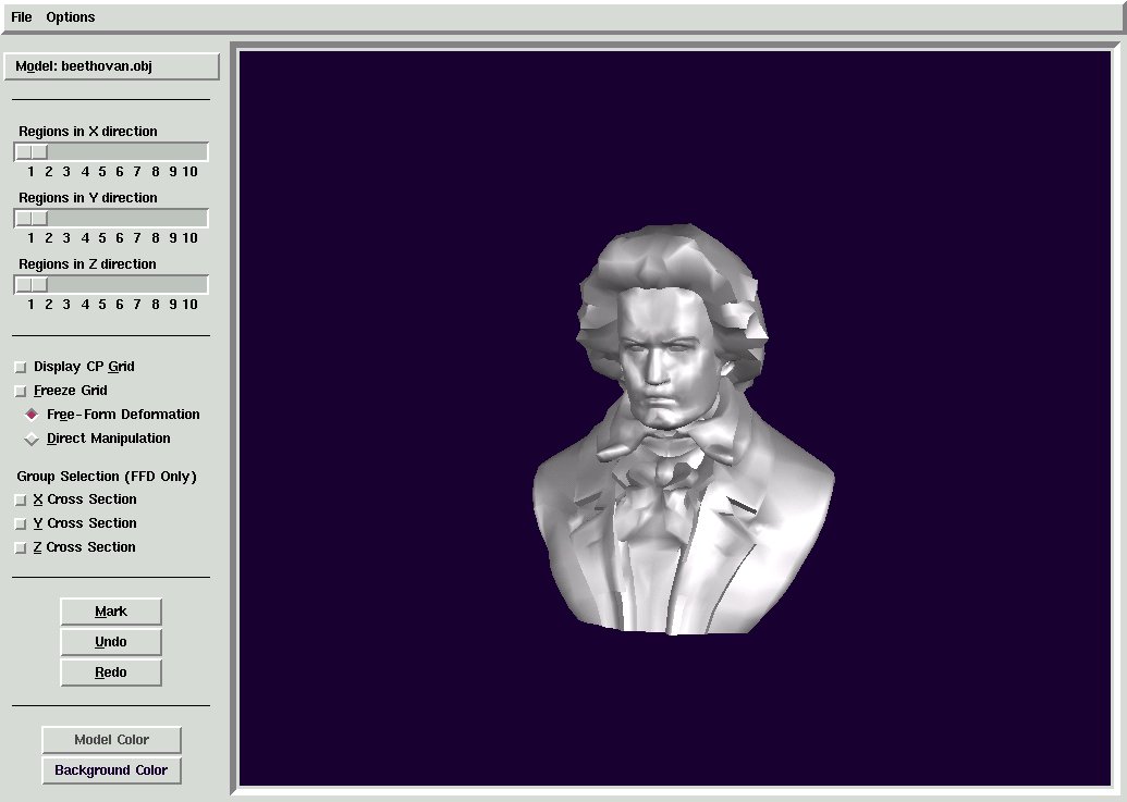
Figure 1: User-Interface for the Free-Form Deformation Program
Direct manipulation is an attempt to make deformations of objects more
user-friendly. The user selects point on the surface of the object and moves
the point to a new location. The program automatically determines adjustments
to the control points that effect this change.
My program has the following main interface features (See Figure 1):
In more detail...
![[JPEG Image]](pic1.jpg)
Figure 1 Beethoven Model before deformation with 4x6x5 lattice |
![[JPEG Image]](pic2.jpg)
Figure 2 Beethoven after a few iterations of FFD |
![[JPEG Image]](pic3.jpg)
Figure 3 Beethoven with multiple points selected for DM |
![[JPEG Image]](pic4.jpg)
Figure 4 Final Lattice after a several more DM steps |
![[JPEG Image]](pic5.jpg)
Figure 5 Final Beethoven model after several rounds of FFD and DM |
![[JPEG Image]](pic6.jpg)
Figure 6 ATC model before deformation |
![[JPEG Image]](pic7.jpg)
Figure 7 ATC after several DM steps with multiple target points |
![[JPEG Image]](pic8.jpg)
Figure 8 Lattice after DM on ATC |
![[JPEG Image]](pic9.jpg)
Figure 9 ATC deformed by several DM steps |
![[JPEG Image]](pic10.jpg)
Figure 10 FFD using an X cross section selection on ATC |
![[JPEG Image]](pic14.jpg)
Figure 11 Deathstar model |
![[JPEG Image]](pic11.jpg)
Figure 12 Deathstar model with 4x4x4 lattice in line mode to facilitate point selection |
![[JPEG Image]](pic12.jpg)
Figure 13 Deathstar partially deformed using FFD |
![[JPEG Image]](pic13.jpg)
Figure 14 The DeathEgg! |
![[JPEG Image]](pic15.jpg)
Figure 15 Triceratop Model |
![[JPEG Image]](pic16.jpg)
Figure 16 Triceratop model showing lattice after a number of DM steps |
![[JPEG Image]](pic17.jpg)
Figure 17 Triceratop after deformation by DM |
![[JPEG Image]](pic18.jpg)
Figure 18 Tie Interceptor Model |
![[JPEG Image]](pic19.jpg)
Figure 19 FFD Deformation with 4x4x3 lattice |
![[JPEG Image]](pic20.jpg)
Figure 20 Resulting model... Beware those hi-G turns! |