CS 779 Course Project
Chris Micacchi
April 25, 2003
Contents
Overview
This project implements Free Form Deformations (FFDs). Free Form Deformations are simply functions that map the points on an input primitive (e.g. a sphere) into a deformed space. In this project the function used is a three-dimensional Bézier tensor product volume.My project is essentially a simple modeling system, in which primitive objects such as spheres, cubes, and cylinders can be created and manipulated. In addition, FFDs can be applied to individual objects, or to groups of objects. The degree of the three component Bézier curves is required to be equal, and is restricted to lie between 2 and 20 (an arbitrary limit, but necessary to allow buffer preallocation). Thus, creating a FFD with "degree" 2 produces a triquadratic tensor product volume with three control points in each axis, for a total of 27 control points across the entire FFD domain volume.
In addition to modeling using FFDs, my project implements an Animation mode, in which the FFD control meshes are treated as a mass-spring system onto which forces may be applied. For simple models the mass-spring system updates are fast enough that one can manipulate the objects interactively.
You can get the source to my project here.
Interface
Viewports

The interface to the program is shown above. From the top left the four viewports are, in clockwise order, front (down the Z axis), side (down the X axis), perspective (camera), and top (down the Y axis).
- Dragging the left mouse button in one of the orthogonal viewports applies the current operation.
- Dragging the right mouse button in one of the orthogonal viewports pans that viewport in the dragged direction.
- Dragging the middle mouse button up or down one of the orthogonal viewports decreased or increases the zoom factor for that viewport.
Modes
The control panel to the right of the viewports lets the user select among the five modes.- Camera
This mode lets the user move the camera position and look-at point. - Model
In Model mode the user can create and transform objects. In this mode the user can also add FFDs to an object or group of objects. A model can have multiple FFDs applied. Selecting multiple objects and then adding an FFD causes the selected objects to be grouped together. The FFD is then added to this group. - Domain
In Domain mode the user can manipulate the region of influence (that is, the domain transformation) of a model's FFDs. - FFD
In this mode the control points of the visible FFDs can be transformed. To make editing easier, FFD control meshes can be individually hidden. - Animate
This mode activates the mass-spring systems attached to the FFD control points. Pressing the "Animate" button enables frame-by-frame updating of these systems. Manipulation to the control points in this mode are not permanent and can be reset by pressing the "Reset Animation" button. The strengths of the springs can be changed, and two external forces (gravity and wind) can be applied to the models.Selecting control points in this mode causes them to become "fixed" in space (that is, they will not move due to applied forces). The standard transformations (translate, etc.) will still move these points, forcing the rest of the mass-spring system to adjust.
Finally, there are two build-in animations that can be applied to the fixed points. The Shake animations oscillate the selected control points with user a specified amplitude and period. The Spin animations rotate the selected control points about their center with a user-specified period.
Operations
In addition, there are four operations that are available in all modes (except in Camera mode, when only Translate is available).- Select
This mode allows the user to select objects for manipulation. Holding Shift and dragging the mouse allows for easy selection of multiple objects. The selection state of any object that is inside the dragged region is toggled.As a shortcut, holding CTRL temporarily switches to the Select operation. Releasing CTRL switches back to the previous operation.
- Translate
The Translate operation allows the user to move all selected objects around in the scene by dragging the mouse in one of the three orthogonal viewports. - Rotate
The Rotate operation allows the user to rotate all selected objects around their local centers by dragging the mouse in the direction of rotation in one of the three orthogonal viewports. - Scale
The Scale operation allows the user to scale all selected objects in the X, Y, and/or Z directions. The current scaling directions are chosen using the Scale Options panel to the right of the viewports. Moving the mouse up in a viewport will increase the scale factor, moving the mouse down in a viewport will decrease it.
Images
Here are some models that I have created to illustrate my system. Note that to change the surface colours, I had to edit the .gr file and modify the gr_material lines directly, as there's no way to do so from within the program.
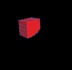
 deg14.gr: A sphere with an undeformed triquatuordecic (degree 14 :) FFD. |
|
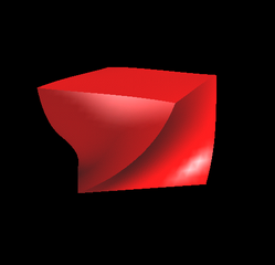
 deg14-a.gr: The same sphere, deformed to make an interesting shape. |
 pillar.gr: This is a model of a fancy pillar. It is made up of six deformed cylinders and one undeformed cylinder. |
|
 head.gr: This model is essentially a sphere that has a number of deformations applied to it to make the face shape. Then four spheres were added to make the eyes and pupils. Three cubes were deformed to make the eyebrows and mustache. The tongue is also a deformed sphere. |
 cylinder.gr: One of these cylinders is actually a deformed cube. Can you guess which one? (answer). |
|
 twist.gr: Rotating horizontal rows of control points can give an object a twisted appearance. |
 |
|
 |
| c1.gr: Two deformed cylinders joined with a C1 join. | ||
 |
|
 |
| c2.gr: Two deformed cylinders joined with a C2 join. | ||
 |
|
 |
| local.gr: An object can have multiple local deformations applied to it. | ||
 |
|
 |
| hier.gr: Groups of objects can be deformed together with a single deformation. The sub-deformations can be seen as greyed out meshes. | ||
 |
|
 |
| phone.gr: This model is based on one shown in [1]. It uses hierarchical deformations to create the final telephone handset, as can be seen in the right image. | ||
 |
|
 |
| flower.gr: A nice flower. | ||
Movies
Here are some MPEG movies of various animations. They were produced by using the Capture feature of the Animation mode, which writes out a sequence of PPM frames. The program ppmtompeg was used to combine these frames into an MPEG movie.
 animcube.gr: A cube falling under gravity. The cube is fixed in the middle of its bottom face. |
|
 animcube.gr: The same cube falling under gravity. In this animation the cube is fixed at one side on its bottom face only. |
 animcube.gr: A cube under gravity spinning around the Y axis. The spinning stops and the cube comes to a rest. |
|
 animcube.gr: A cube under gravity shaking violently in the Z axis. Quite rapidly the motion of the mass-spring system reaches harmony with the shaking, producing increasingly large movements in the system. Even after the shaking stops the system continues to oscillate until the structure collapses. |
 floppytorus.gr: A floppy torus. |
|
 predeformed.gr: The model being animated can be pre-deformed using the normal Deformation mode. However, deformed models may not be able to maintain their shape against strong forces. For example, turning a cylinder into an cone pointing down and then expecting the cone to support itself against gravity is only possible with extremely stiff springs. |
 cloth2.gr: A cube squashed extremely flat. One end is fixed and the cube is subjected to gravity and wind forces. |
|
 merrygoround.gr: This model is composed of a number of deformed and undeformed primitives grouped into a single deformation. |
Summary
My base project was to implement Free Form Deformations using Bézier tensor products.
My extras are as follows.
- Animation mode, in which mass-spring systems are attached to the FFD control meshes and are updated on-the-fly in response to user input (such as translations) and built-in forces and animations.
- Hierarchical deformations of groups of objects (up to 5 levels deep).
- Local deformations (manipulating the deformation domain transformations directly).
- Multiple objects/control points can be selected and manipulated simultaneously.
- Easy-to-use interface, including toggleable display of individual FFD control meshes to cut back on clutter, toggleable quality of primitives for speed of render versus quality of image, and various other niceties.
- The head, pillar, and flower models and the various animations.
References
[1] Thomas Sederberg and Scott Perry. Free-Form Deformations of Solid Geometric Models. Computer Graphics, 20(4): 151-160, 1986.[2] Alan Barr. Global and Local Deformations of Solid Primitives. Computer Graphics, 18:12-29, 1984.
[3] Andrew Witkin and David Baraff. Physically Based Modelling. SIGGRAPH 2001 Course Notes, 2001.