Overview
The objective of my project was to implement a modeling program providing a mechanism for applying subdivision surface techniques to meshes. The program features a simple user interface with two sub windows. The first sub window displays the current model. Interaction with the model is controlled by cursor motions over this window. The second window is the tools window, which is used to control the current mode of interaction with the model window and to toggle display features. Both windows can be moved freely.
The three interaction modes are view, shape, and colour. In view mode, the user can rotate the model and translate it along the view axis. In shape mode, the user can reposition the vertices of the model's underlying mesh. In colour mode, the vertices can be coloured with arbitrary RGB colours. All actions are performed by mouse motions.
In addition to these controls, the program features a command console. The command console accepts user commands which process the model, reshaping its mesh, colouring its vertices, or texturing its faces. Furthermore, the user can load and save .off file models through the console.
Features
Loading Of .OFF Files With Complex Meshes
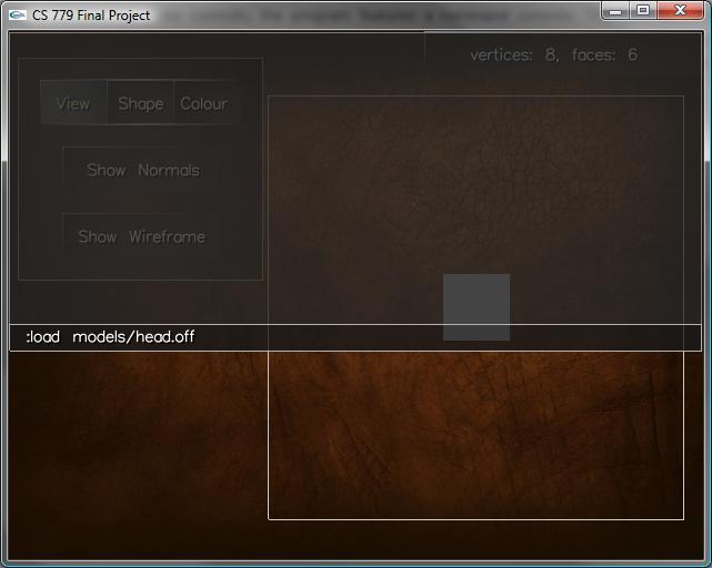
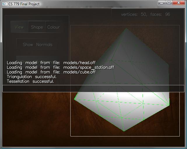
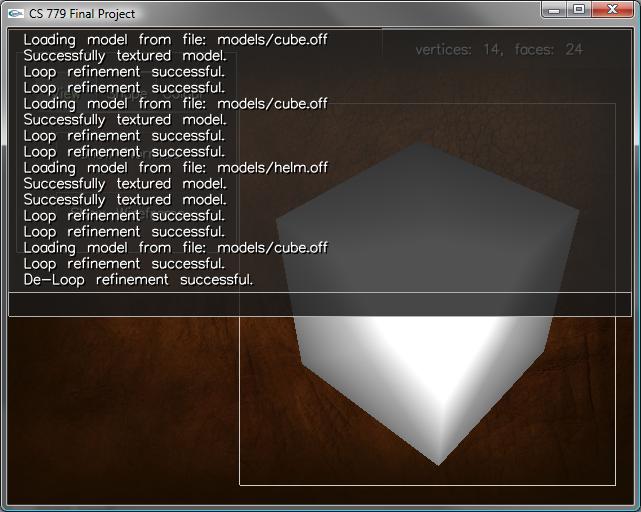
The above figure illustrates the program's command console. The shown command is used to load a model of a head stored in Object File Formate (OFF). The default rendering of this model is shown below.

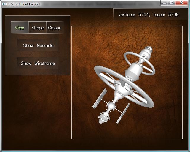
Complex meshes with arbitrary degree faces can be loaded correctly. Faces with degrees higher than four are decomposed into a set of triangle primitives for rendering using OpenGL. The following figure demonstrates the loading and rendering of a high-genus mesh, consisting of several different high-degree faces.
Tessellation And Triangulation Of Faces
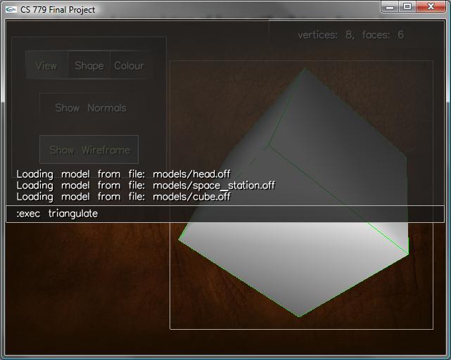
In addition to loading models, we can specify commands to process the model's geometry. The above command triangulates the geometry by introducing a new vertex at the centroid of each non-triangular face. The triangulation of the cube is shown below with the wireframe included in the rendering.
Similarly, triangle faces can be tessellated to an arbitrary level of detail by executing a tessellation command. This command executes a four-to-one subdivision.
Loop Subdivision Surfaces
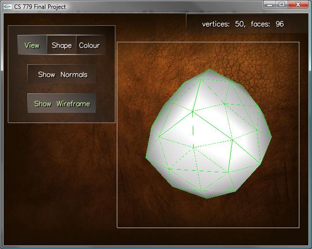
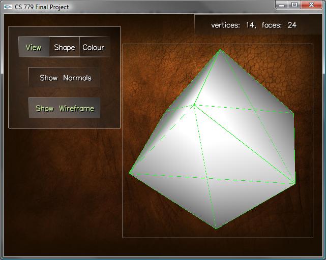
As the primary objective of my assignment, I implemented the Loop subdivision surface scheme. The above figure shows one level of Loop refinement applied to the cube. All introduced (ordinary) vertices have six neighbouring faces and vertices.
We can repeat this refinement process to achieve surfaces with continuity at each point up to first derivatives and second derivative continuity everywhere except at the extraordinary points. The extraordinary points correspond to vertices with degree other than six, a subset of the vertices of the original control mesh.
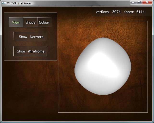
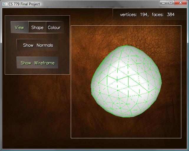
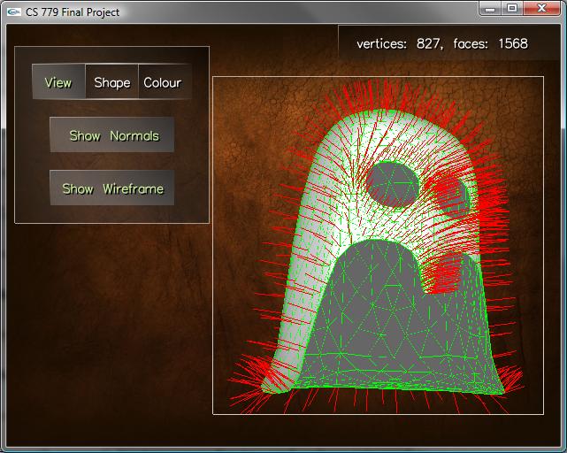
At each level of refinement, the normal vectors to each vertex are approximated by averaging the normals to their incident faces. The produces nice smooth shading along the highly refined models. The following figure illustrates the computed normals with with red lines. Notice also that the surface is not closed and has been smoothed nicely around its boundaries.
Root-3 Subdivision Surfaces
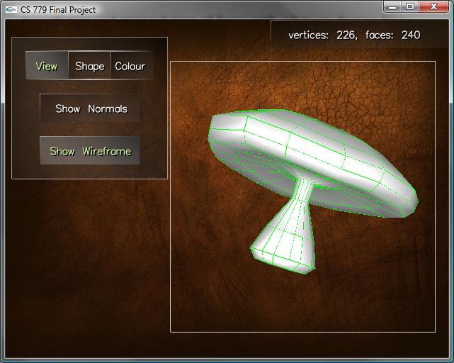
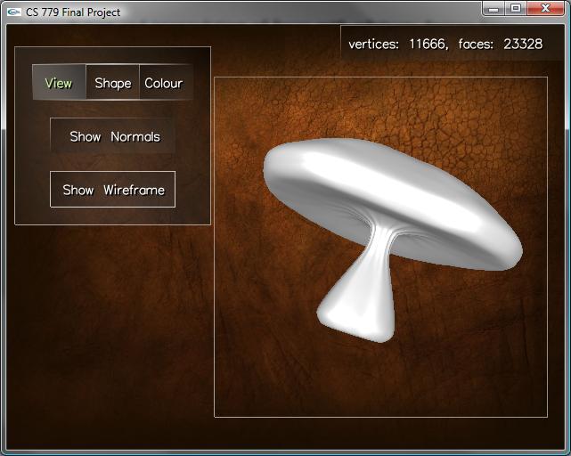
As the secondary objective to my project, I implemented the √3 subdivision scheme. This scheme works similarly to Loop in that it produces smooth triangular meshes with similar continuity result. However, the subdivision component of the refined performs a three-to-one subdivision of each triangle and flips edges, as opposed to a four-to-one triangulation like in Loop's scheme. This difference gives a slower blow up in the number of triangles and can be combined with adaptive techniques to produce smooth subdivided surfaces with relatively few triangles. The following figure shows the result of multiple refinements to the above mushroom mesh.
Catmull-Clark Subdivision Surfaces
As my first extra, I decided to implement the Catmull-Clark subdivision surface scheme. This scheme is one of the earliest and produces quadrilateral faces as opposed to triangles. It's smoothness results compare to those of Loop sudivision surfaces. All schemes were similar in their difficulty to implement and had efficient run times. Though, the √3 subdivision and Loop subdivision schemes do a better job at retaining characteristics of the original shape and and produce triangular meshes which have several advantages over non-triangular meshes.
Repositioning And Colouring Of Vertices
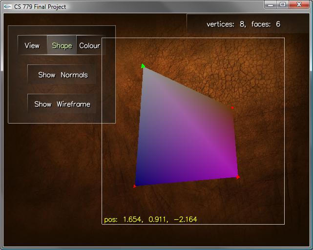
As another extra feature, the program feature two additional modes of interaction. The shape mode allows the user to reposition vertices along a plane through the vertex and parallel to the current view plane and along the direction normal to the view plane. This mechanism was useful for manipulating the shape of a basic control mesh. By a similar operation, the user can modify the hue, saturation, and luminance of the vertex colours while in colour mode.
Smooth Normal, Texture Coordinate, And Colour Interpolation
After reshaping and colouring the
control mesh, the user can execture the subdivision surface schemes to
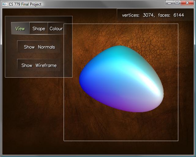
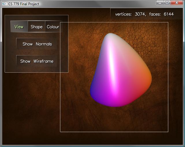
produce a smoother model resembling the shape of the control mesh. The
vertex colours of this refined mesh are interpolated using a similar
smoothing technique to the chosen method of subdivision. As will be
shown illustrated later, existing texture coordinates are also
interpolated during subdivision.
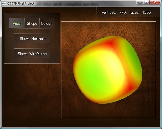
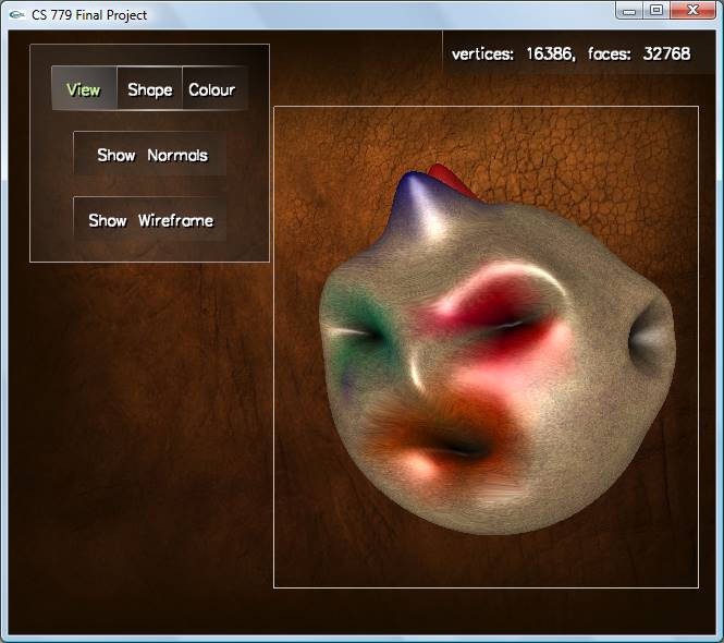
Gaussian curvature vertex colouring
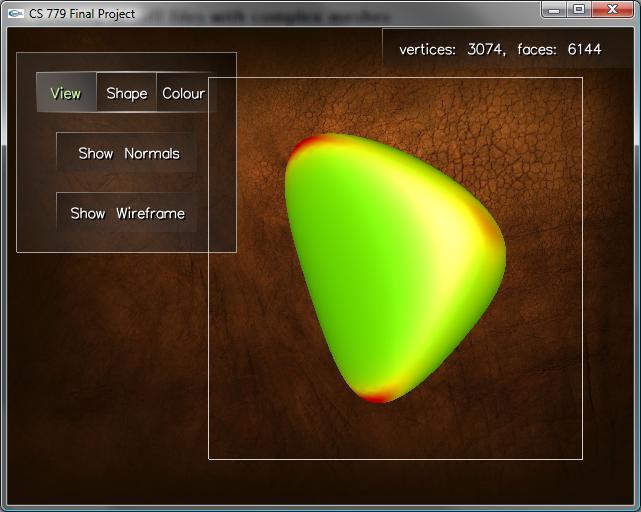
As an extra, I implemented a procedure that computes an approximation to the Gaussian curvature at each point using the Gauss-Bonnet method. The algorithm produces accurate approximations for triangle meshes. After computing the curvature, I map the values to a hue and colour each vertex according to this computed hue value, as shown above and below for two subdivided meshes.
Inverse Loop Subdivision
The Loop subdivision schemes works by subdividing each edge of the control mesh and computing new positions for each vertex in the subdivided mesh. The new positions for the original vertices depends only on an affine combination of themselves with their neighbouring vertices in the original mesh. The weighting of this combination depends only on a the degree of the vertex, which is invariant throughout subdivision. Thus, we can construct a sparse matrix whose left multiplication with a vector of the original vertices produces a vector of the new vertex positions. Furthermore, as this matrix is square and has linearly independent rows, it is invertible. Using this result we can perform an inverse Loop subdivision operation to compute the control mesh of a subdivided mesh, without any explicit knowledge of the original mesh. This can be done by a breadth-first search of the subdivided meshes vertices to compute to isolate the vertex points from the edge points. The following figure demonstrates the inverse Loop subdivision operation applied to a subdivided cube.
Automatic Texture Coordinate Generation
As my final feature, I implemented the ability to render textured meshes and to automatically generate texture coordinates. The basic scheme for texture coordinate generation works by linearly mapping each vertex point to a fixed plane and computing the coefficients of a linear combination of two fixed normal vectors on this plane that result in the projection of that vertex point onto the plane. These two coefficients are then mapped to the texture coordinates at the vertex. Given the normal to the plane, this computation simplifies to a few initial cross products and two dot products for each vertex. Finally, assuming that the texture tiles along its horizontal and vertical axis, the texture mapping is guaranteed to produce a contiguous alignment of the texturing of each face (since the texture coordinates at each vertex are coincident). However, since the texture coordinates of a given face are separated proportional to how parallel their face is with the texturing plane, nearly orthogonal faces can have a distorted texturing.
As a first attempt to remedy this problem, I developed a method to approximate the optimal texturing plane. The method is a randomized numerical method that is both extremely accurate in practice and requires only a constant number of iterations. Thus, it is an effective method to generate an optimal linear mapping of texture coordinates that requires time proportional to the number of vertices in the mesh. The method works by generating random normal vectors until it computes the vector whose minimum absolute cosine pf the angle between all other face normals is minimized.
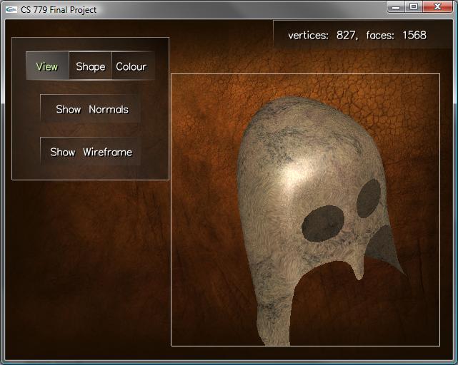
Though extremely effective for rough meshes, this method, as with any linear mapping technique, produces poor results smooth meshes. Since the normal vectors of smooth meshes tend to cover the unit sphere, the minimal set of nearly planar faces have a distorted texturing. To solve this issue, we notice that the interpolated texture coordinates of a Loop subdivision surface preserve contiguity with little distortion. Thus, we can generalize the linear mapping technique to smooth meshes via Loop subdivision surfaces. That is, given a smooth mesh, we attempt to construct a rough control mesh that can be textured using the linear mapping. To achieve this, we can modify the smooth mesh to have triangular faces that correspond to a Loop subdivision, and apply the inverse Loop subdivision operation. We then repeat this process until the faces achieve a specified degree of orthogonality. Finally, we texture the unrefined mesh and then apply the Loop subdivision surface scheme to reconstruct the original mesh. An example of a smooth mesh textured via this method is shown below.
But, though this method is very effective, it is more computational intensive than the linear scheme, which can still produce good results as shown below.
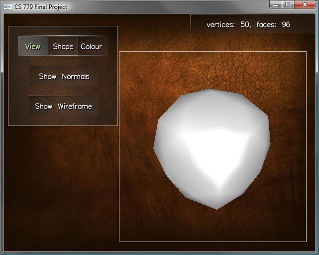
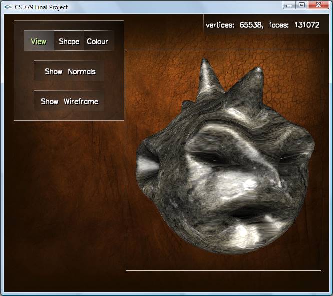
A Sample Model
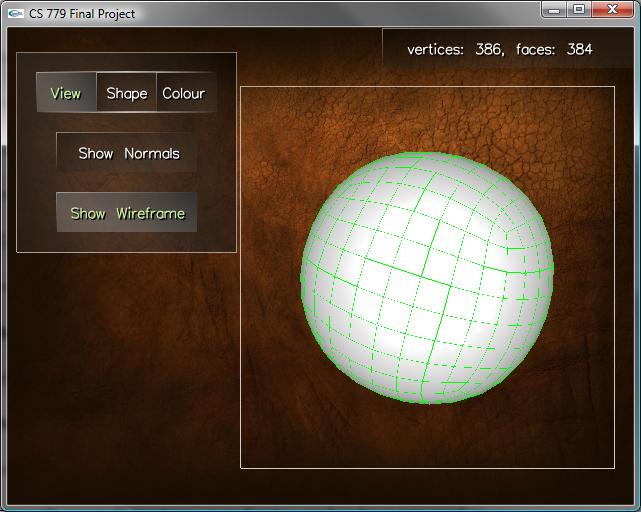
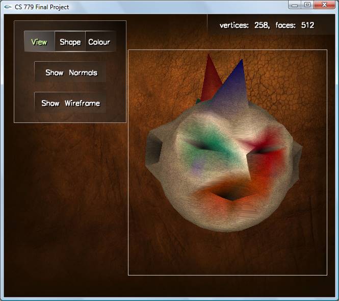
The following model was constructed in my program starting initially with a sphere consisting of 258 vertices.
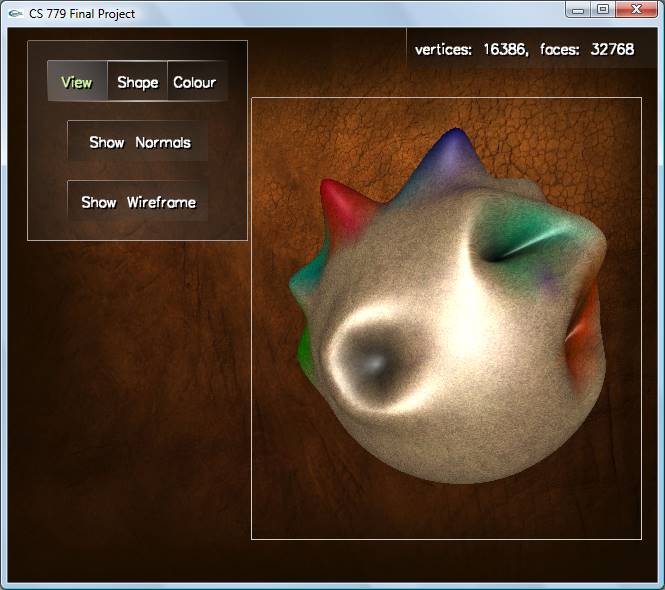
And, with a little Loop subdivision surface refinement...
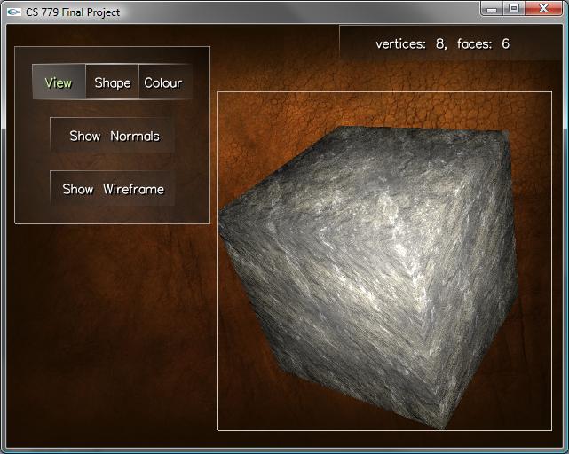
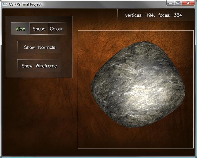
Or, we can make the model out of rock.
Implementation
The modeling program is implemented in C++. With the exceptions of the standard C libraries, OpenGL, and GLUT, the code is entirely original. It features a GUI system for constructing windows, buttons, and icons that provides a mechanism for propagating input events to different GUI controls. Furthermore, I implemented several utility libraries for performing vector operations, converting between coordinate systems, solving matrices, manipulating strings, converting color formats, loading images, and creating textures.
Specific to the application, I created an geometry library and model class. The model class encapsulate the rendering of its geometry, the models animation, the selection of its vertices, and the rendering of additional information about the underlying geometry (such as the normal vectors). The geometry library provides several classes for encapsulating geometric data in various structures to provide both efficiency and power. Most important for the subdivision schemes was the Mesh structure, which implements a variant of a winged-edge data structure. The Mesh structure provides methods to
- add vertices with arbitrary (x,y,z)-coordinates,
- add convex faces of any degree,
- compute face and vertex normals,
- generate texture coordinates
- apply Loop, Catmull-Clark, and Root-3 subdivision surfaces
- scale, center, triangulate, and tessellate the geometry
- compute and test against the geometry's bounding box
Data Structures
As mentioned in the previous section, I implemented a variant of a winged-edge data structure. Like the winged-edge data structure, I provide an array of edge objects which can be used to find the incident vertices and faces to a given edge. Furthermore, each vertex stores its incident edges and faces, and each face stores its incident edges and vertices. However, I do not use simple linked lists to store the incidences and instead use an array-based method. This array-based implementation allows for more efficient traversal of the vertices, edges, and faces but comes with added complexity for the construction of the geometry. When adding faces to the mesh, the incidence lists have to maintain a counter-clockwise order. To achieve this insertion I use a lazy re-ordering insertion that yields an amortized cost to insert faces proportional to their degree. Empirically, I am uncertain of the exact performance advantages/disadvantages of this alternate construction, but since all incidences of a given object are stored in contiguous memory, I would expect that accessing the structures data would be faster. In either case, the program runs at very high frame rates without the use of any hardware tricks for buffering the geometry.
What I learned
In the process of implementing my project, I learned about the effectiveness of some subdivision surface techniques. The schemes run very efficiently and produce nice looking results for most meshes. Furthermore, I learned about the mathematical reasoning behind these schemes and why they achieve their level of continuity. Moreover, I learned why naive approaches to creating smooth meshes and subdividing triangles can produce poor results.
In addition to learning about the behaviour of these schemes, I realized the motivation for why achieving certain continuity results is desirable. I noticed that a naive subdivision implementation with discontinuous first derivatives at extraordinary points produces poor quality meshes.
In implementing and deriving a texture
mapping scheme for arbitrary meshes, I developed an understanding of
what criteria make the texture mapping look nice, and what this
corresponds to mathematically. I derived linear texture mapping scheme,
that produces fully contiguous texture coordinates with minimal
distortion in the linear setting. This scheme produces very good
results for meshes without smooth corners. That is, the less the set of
face normals cover the unit sphere, the better results the scheme
produces. Furthermore, noticing that applying Loop subdivision to a
rough mesh yields good texture coordinate interpolation, arbitrary
meshes can be textured well by first texturing a rough approximation to
that mesh than using Loop's scheme to approximate the smooth mesh more
closely. To find this rough approximation, I found applying the inverse
of Loop subdivision worked well.
Finally, I learned about the tedious debugging issues that often arise when using a complex winged-edge-like data structure.
Objectives Summary
- Loading of .off files with simple and complex meshes
- Tessellation and triangulation of faces with arbitrary degre
- Loop subdivision surfaces
- Root-3 subdivision surfaces
Extras
- Smooth normal, texture coordinate, and colour interpolation
- Catmull-Clark subdivision surfaces
- Gaussian curvature vertex colouring
- Repositioning of vertices about the current view frustum
- UI feature for colouring vertices
- Automatic texture mapping using an optimal linear map
- Inverse Loop subdivision
- Researched various schemes for texturing objects and created a novel approach
- High performance implementation with winged-edge data structure variant