Overview

This project implement Free-form Deformation(FFD). FFD is a modeling tool that can be applied to various types of solids and surfaces. Models are mapped to a deformed space and reconstructed by evaluing a tri-variate B-spline tensor product.

The knots vectors used are uniform except at the ends where both ends has multiplicity 3 to ensure that the image of the B-spline is the convex hull of the control lattice.

Core Objectives

  1. Primitive support
    • cube, sphere, cylinder, torus
  2. Rotation of model
    • Rotation of object and control points via virtual trackball
  3. Control points selection
    • In ‘select’ mode, double click control points to select/deselect point. Drag to toggle the selection of all control points within the rectangle defined by the drag
  4. Normal calculation
    • Vertex normals are calculated every step to ensure smooth shading
  5. Object Deformation

Extra Objectives

  1. Save/Load .obj
    • Files of .obj format can be loaded (i.e. need to contain normal information). The current deformed object can be saved into .obj format
  2. Control point dimension
    • Number of control points in in each dimension can be changed.
  3. Camera view and FoV setting
    • Shortcut of viewing different faces of the object. Camera FoV and be adjust as well
  4. Undo and Redo
    • Action can be undo and redo with shortcut ‘U’ and ‘R’
  5. Control points and object visibility
    • Control points and object can be hided to give better view of the other
  6. Direct manipulation
    • Closest vertex in the object is used for the direct manipulation
  7. Bend and Twist
    • Gestures of bend and twist are recognized.

Discussion

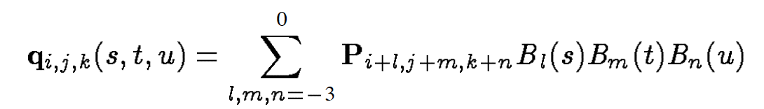
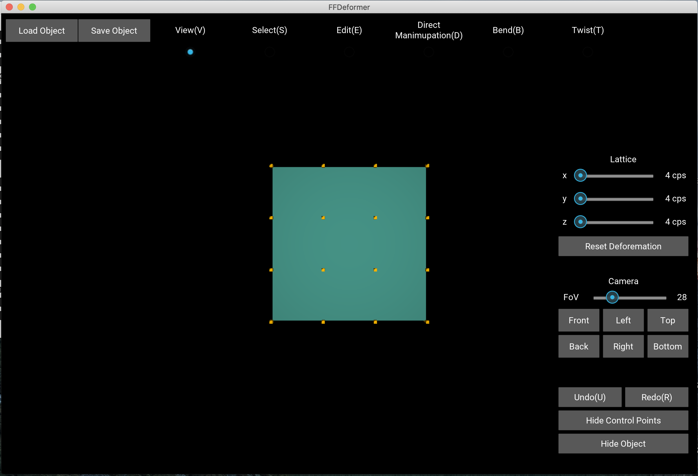
Mapping from 2D to 3D: There is ambiguity when mapping a vertex's screen position to its position in model space. When single point is selected, the mapping is done by transforming the vertex position(3D) and the displacement(2D mouse movement in screen space) into clipping space and combine these two, assuming no depth displacement. And the result is then transformed back to model space. This method ensures that the displacement in screen space of the control point is exactly the displacement of the mouse. However, when multiple control points are selected, the z-value of the control point that is closest to the view direction (in clipping space) is used for movement of all control points. In reality, this is more intuitive.

Stroke segment for bending: In Draper and Egbert's paper, the stroke is divided to segments of equal distance. However, for Kivy(i.e. graphics kit used for the project), the mouse_move event is not recorded frequently, hence it is hard to obtain equal-distanced segements. Therefore, the recorded mouse position is uniformly sampled. The result of this solution will therefore be affected by the speed of the mouse stroke. Which might be desired in some cases.

.obj file processing: .obj files does not provide a 1-1 mapping from vertex to normal, which is less ideal for the purpose of performing FFD. The approach I took is to first build a 1-1 map of vertex and normal and use this map to perform the FFD. Only indices of vertices are stored for every faces, and the normals are then retracted from the map.

Normal Calculation: There is no direct methods of calculating normals for a tri-variate tensor product at a single point. The approach I took is that for each vertex, first find two vector spanninf the tangent plane at that point. Then two points are chosen epsilon-distance along each vector from the vertex. This face (vertex+two extra points) therefore captures the local curvature of the surface. The three points are deformed together. The new normal of the vector is assigned to be the normal of this deformed face. In practice, this gives faily smooth shading result.

Bug & Improvement

Extra triangles from control points to center of the model space: When triangles defining a mesh are small, undesired behaviour is observed. THis addition of triangles are random. It is unclear that if this is related to unrobustness of Kivy (graphics kit), since this kit is faily new and is less supported for 3D graphics.

Extra surface support: Free-form Deformation can be applied to various surfaces, it is desired to add support for more types of surfaces (e.g. Bézier patch, tensor product patch etc.)

Multiple point constraind for direct manipulation: Currently the program only support single point constraint.

Transformation of object: Currently the object can only be rotated, it would be better if object can be scaled and translated.

Results

Fig.1 - User Interface
Fig.2 - Control Point Selection
Fig.3 - Direct Manipulation
Fig.4 - Bend
Fig.5 - Twist