Hierarchical B-Spline Surface Editor
Scott Larter
Overview
For my CS
779 final project, I implemented a Hierarchical B-spline surface editor. This
project was based on the 1988 paper, Hierarchical B-Spline Refinement, by David
R. Forsey and Richard H. Bartels [1]. In this paper, they address the issue
that editing a tensor product surface generally has a global effect on the
surface and most of the time, many control points outside of the region of
interest are changed along with the few control points within the region we
wish to edit. Forsey and Bartels introduce a method of refinement using
overlays, hierarchically controlled subdivisions, to localize the influence of
editing a tensor product surface. As in the paper, my editor implements a
B-spline surface with uniform knot vectors.
My editor was created with C++ and OpenGL, using the
gluNurbsSurface function to render the B-spline surfaces. Additionally, I used
GLM, a C++ header library, and the Eigen3 library to assist with matrix and
vector operations.
Features
When the editor is first run, it produces a flat 11x11
B-Spline surface centered at the origin with uniform knot vectors. The user can
press ‘c’ to toggle displaying the control points.

The user can left click on a control point to select it and
can move it around by holding the left mouse button and dragging the mouse.
This will edit the surface in the classic non-localized way. Selected points will
turn red. Point selection was implemented by casting a ray through the scene
and testing for intersections. The gluUnProject function was useful for
transforming screen coordinates to model coordinates.

Local
Refinement
Localized
refinement is implemented through the use of overlays. An overlay can be
thought of as a sub-surface (or child surface) with its own control points that
is dynamically tied to its parent surface through offset referencing. To create
an overlay, the user must define a region on the surface by selecting its
corner control points. The first corner point is selected with the left mouse
button as before, then the second corner point is selected with the right mouse
button. Once a region is defined, an overlay is automatically created with its
control points displayed. The grey control points cannot be moved to maintain
continuity with the parent surface. The user can choose to only display the
control points at a specific refinement level and can navigate through the
different levels using the ‘w’ key (up) and the ‘s’ key (down). Note that the
‘c’ key will toggle displaying the control points at ALL levels of refinement.
The paper restricts the two corner control points of an
overlay to be at least two points apart and not colinear. The overlay must also
be completely contained within the same level of refinement. The parent surface
is trimmed to allow the overlay sub-surface to be rendered within the parent
properly.

Once the overlay is created, its control points can be moved
by clicking and dragging the left mouse button to create a more localized
change in the surface.

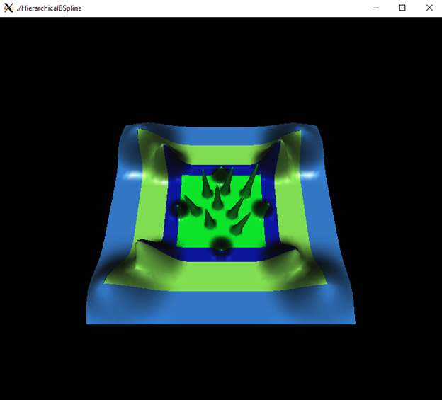
Of course, overlays can be created within other overlays,
thus creating a hierarchy of refinement levels as shown below.
Offset
Referencing
Each control point, at any refinement level, is represented
in reference-plus-offset form to ensure that local refinements are preserved
when changes are made to the surface at a lower level of refinement. The
reference component of the point is a dynamic reference to its parent surface
and the offset component stores the relative changes made to the point itself.
In the pictures below, the right picture shows the same local changes as the
left but with changes made to the base surface.

Edit
Points
When editing
a surface, it is often easier to directly manipulate points on the surface
rather than moving around control points. This provides more intuitive control
over the surface and avoids undesired changes made to the surface. In the
paper, the authors refer to these points on the surface as edit points. Each
control point (except for the outer points) has an associated edit point that
lies on the surface which is the surface point that is maximally influenced by
that control point.
In my editor, to switch to viewing and manipulating edit
points, the user simply clicks the middle mouse button and selects Edit Points
from the menu.

The editor now displays the associated edit points on the
surface that the user can left click and drag to directly manipulate the
surface. Overlays can also be created in the same way in Edit Points mode. To
return to Control Point mode, the user can middle click and select Control
Points.

Patch
Merging
The user can create overlapping overlays and they editor will
automatically merge the overlapping patches to create one overlay that
completely contains both of them. In the picture below, there is one existing
overlay on the base surface and the user is about to create an overlapping
overlay that has one of its corners within the existing one (selected red
point).

In the next picture, the user has defined the second corner
of the overlapping overlay and the editor automatically merged the two patches
into one region that completely encompasses both overlays.

Merging patches will preserve edits made to the existing
overlay. It will also preserve any child overlays defined on the existing patch
and all the changes made to them as shown in the two pictures below.

Future
Work
·
Creating
interesting models with different layers of refinement
·
Saving
and loading user sessions and models
·
Trackball
movement of the camera around the surface for easier refinement
References
[1] D. R.
Forsey, R. H. Bartels, "Hierarchical B-Spline Refinement", ACM
Trans. Comput. Graph., vol. 22, no. 4, pp.
205-212, 1988.