![[UW shield]](http://www.uwaterloo.ca/images/UWlogo.GIF)

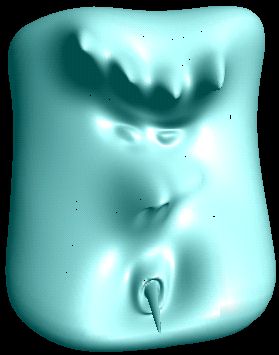
Click on the above images for a quick-time movie of the surface being progressively loaded.
To simplify the code, I used only uniform bicubic B-Spline patches in the project. I also used the Forsey and Bartels overlay creation method which created 49 control points for each overlay. Although you can use 25 control points to represent an overlay, it would require you to traverse up the tree when evaluating each edge patch. Using 49 points simplified the code immensely.
One of the difficulties of modelling with hierarchical B-splines is how to manipulate the control points at the different overlay levels in order to shape objects. The easiest implementation would have been to force the user to create the lower overlays first before creating overlays at a higher level. This would have been very frustrating to users who want fine detail but don't want to go through all the grudge work of creating the different overlay levels. To alleviate this problem, I mapped the keys 0-9 to the different overlay levels and allow the user to create a new control point by simply selecting a point in the current overlay level, switch to the level where they wish to create a new control point and then just move the mouse to create the new control point. The intervening overlays are created automatically.
Although there may be many control points created at each overlay level, only a few of them contain useful information(ie. have offset values). The other control points can just be re-calculated. So instead of saving or transmitting all the control points, we can just keep the ones that have non-zero offset values. The problem is, how do we re-create the tree structure since we are not saving all of the control points? One way is to record the path needed to recreate the control point P.
*----*----*----------*
|00  |01  |1         |
|    |    |          |
*----*----*          |
|02  |03  |          |
|    |    |          |
*----*----*----*-----*        * = control points
|2        |30  |31   |
|         |    |     |
|         *----*-----*
|         |32  |33   |
|         |    |     |
*---------*----*-----*
Since we refine an area by halfing, then we can use this to uniquely identify which parents need to be created in order to re-create the required control point. Each square is subdivided into 4 as we move down the hierarchy. We number each of the squares from 0 to 3 and descend the tree to P. Now to recreate P, we just follow the path and create the parents and surrounding siblings necessary at each level until we have recreated the control point. If the number of root patches is of size n, then we only need log(n)+1 + 2*depth bits to define the position of a control point. This is assuming that the root patches are stored in an array and we record a reference into that array. Storing the control points in this manner also allows us to recreate the control points in any order we wish.
I have implemented all of the above in my program although the file format is ascii text to make it easier to debug. I did not have time to implement the socket code to allow transmission of models over a network, but I have simulated the gradual refinement process by creating delays when loading a file so that only portions of the file are loaded at a time.