The trains found in the realtime lab are a standard Märklin HO scale train system, controlled using a digital interface.
The control unit, placed next to the track, is used to both control the trains manually and to interface with the Eos computers. This unit maintains a constant AC voltage on the track and also uses the track to transmit digital signals to decoders located on trains and switches. These decoders ensure guaranteed error free delivery of message packets across an extremely noisy transmission medium.
Different interfaces could potentially be connected to the control unit. The keys on the unit itself can be used to control the locomotives. A separate unit could be purchased to control the switches, but this has not been done since control of all track activities will be performed by the Eos machines in this course. On the current track, the only interface connected to the control unit is that used for computer control.
The keys on the control unit provide the following functions:
The interface unit is connected to the Eos computer via an RS232 serial connection. See the hardware section for details on sending and receiving data along the serial connection. The connection should be set to 2400 baud with 1 start bit, 2 stop bits, 8 data bits and no parity check. The following code can be used to set this up:
/*
 *      XON8250_PORT_INIT (Cmd) configures the 8250
 *        cmd is a string of the form baud parity stop data ... i.e.
 *        300 n 1 8
 *
 *        baud - 300, 600, 1200, 2400, 4800, 9600, 19200
 *        parity - n -> no parity check   0
 *                 o -> odd parity        1
 *                 e -> even parity       2
 *        stop   - 1 -> 1 stop bit
 *                 2 -> 2 stop bits
 *        data   - 5, 6, 7, 8 data bits
 *
 * Note: This assumes polled IO, not interrupt driven.
 *
 */

void nsc8250_port_init(
                u_short port, /* base address in IO space for serial port */
                unsigned int baud,
                unsigned int data,
                unsigned int parity,
                unsigned int stop)
{
        unsigned mode_word;

        stop = ((stop-1) & 1);
        stop <<= 2;

        baud /= 10;
        baud = 11520 / baud;

        parity <<= 3;
        parity &= 0x018;

        data -= 5;
        data &= 3;

        mode_word = data | stop | parity;

        outb(port + LCR, inb(port + LCR) | LCR_DLAB);
        outb(port, baud % 256);
        outb(port + 1, baud / 256);
        outb(port + LCR, mode_word & 0x7F);
        /* turn on DTR and all other outputs (harmless) */
        outb(port + MCR, 0x0F);

        /* turn off all interrupt sources */
        outb(port + IER, 0);

        /* turn on FIFO, but tell it to make interrupts (if they
         * were enabled when the FIFO has one item.
         */
        outb(port + FCR, 0x0f);

        /* Read pending input and status bits (ignore them)... */
        inb(port + LSR);
        inb(port + MSR);
        inb(port);
}
Commands are sent to the interface through the serial connection in byte-sized packets. A listing of all commands available is presented below:
| Byte 1 | Byte 2 | Command |
|---|---|---|
| 00 00 00 00 to 00 00 11 10 | Train address 1-80 | Set speed |
| 00 00 11 11 | Train address 1-80 | Reverse direction |
| 00 0x .. .. | Train address 1-80 | Set auxiliary function to x |
| 00 10 00 01 | Switch address 0-255 | Set switch to straight |
| 00 10 00 10 | Switch address 0-255 | Set switch to curved (branch) |
| 00 10 00 00 | N/A | Turn off solenoid |
| 11 00 00 01 to 11 01 11 11 | N/A | Read a single sensor module (1 to 31) |
| 10 00 00 01 to 10 01 11 11 | N/A | Read the first N (1 to 31) sensor modules |
| 01 10 00 00 | N/A | Go |
| 01 10 00 01 | N/A | Stop |
An emergency stop can be triggered by sending byte 0x61. This corresponds to pressing the "stop" button. Character 0x60 corresponds to pressing the "go" button and will resume track operation.
Two bytes must be submitted for train control. The first byte must be in the range 0..31 and contains operating data (see table above). The second byte is a train address in the range 1..80.
Switches are controlled similarly to trains. The data character is set to either 34 (curved) or 33 (straight). The address character can be in the range 0..255.
After throwing a switch, the solenoid in that switch will be turned on. You must turn the solenoid off again after throwing the switch. This must be done at least 150 milliseconds after the last switch was thrown, and no more than 500 milliseconds after throwing the last switch. In order to issues this command the character 32 must be sent.
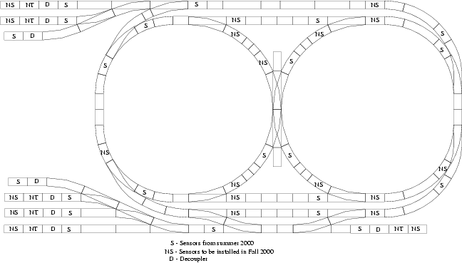
The sensors are located at discrete points along the track and record the direction of any train passing over them.
The state of the sensors is accessed through an s88 feedback module. Each of these decoders can be connected to up to 16 sensors. They are then connected in a daisy chain to the interface unit.
You can read sensor modules individually or read a group of modules at a time. Two bytes are sent back for each sensor module queried. The first byte represents the upper 8 sensors (9-16), the second byte represents the lower 8 sensors (1-8). Each bit corresponds to whether the sensor is currently triggered or not. The two directions of a physical sensors can be thought of as two different virtual sensors, and are labeled as such on the track.